Lesson Overview
The student should develop knowledge of the elements related to airport, runway and taxiway signs, markings, and lighting as required in the ACS/PTS.
References : Airplane Flying Handbook (FAA-H-8083-3C), Pilot’s Handbook of Aeronautical Knowledge (FAA-H-8083-25C, page(s) 14-5,14-16), Parts 91 and 135 Single Pilot (AC 91-73B), Standards for Airport Markings (AC 150/5340-1L), Standards for Airport Sign Systems (AC 150/5340-18F), Airmans Information Manual (section(s) 3)
| Key Elements |
|
| Elements |
|
| Schedule |
|
| Equipment |
|
| IP Actions |
|
| SP Actions |
|
| Completion Standards |
The student understands the meaning of airport, runway and taxiway signs, markings, and lighting and can safely and properly utilize them, thus helping to avoid runway incursions. |
Instructor Notes
| Attention |
Looking outside now (or on the next flight), make note of the number of signs, markings and lights you see. How many of them do you understand? How many are unfamiliar? |
| Overview |
Review Objectives and Elements/Key ideas |
| What |
The markings and signs used at airports, which provide direction and assist pilots in airport operations. |
| Why |
Understanding the markings and signs will greatly assist in avoiding runway incursions and provide the ability to more easily maneuver throughout any airport complex. |
Lesson Details
Runway Incursion Avoidance
Knowing the runway and taxiway markings and signs are a key component of avoiding runway incursions. Avoidance of incursions is an area of emphasis and is critical to save operations. There are various techniques and practices that can be adopted to minimize or eliminate incursions.
Be aware of the airplane’s position at all times, and be aware of other aircraft and vehicle operations on the airport surface. Listen to radio calls and mentally form a 3D picture of other traffic on the airport surface.
As the aircraft is taxied read back all runway crossing and/or hold short instructions. Have a taxi diagram in hand, and review it prior to taxi operations, before landing, and as needed during taxi. However, limit the amount of "heads down" time looking at the taxi diagram so that a hazard is not created. Review NOTAMs and information regarding taxiway/runway closures and construction areas, and identify any affected areas on the taxi diagram.
Know the airport signage, and request progressive taxi instructions if there is any doubt as to the correct taxi route. Turn on aircraft lights and the rotating beacon (or strobe lights) to make the aircraft more visible. Check for traffic before crossing any runway hold line, and before entering any taxiway. When landing clear the runway as soon as possible then wait for taxi instructions.
Study and use proper phraseology, and write down complex taxi instructions at an unfamiliar airport. In the absence of a control tower always look both ways to ensure that the area the aircraft is about to occupy is free and clear.
Runway Markings
There are three general types of runway markings : visual, non-precision instrument, and precision instrument.
| Element | Visual Rwy | Non-Precision | Precision |
|---|---|---|---|
Designation |
X |
X |
X |
Centerline |
X |
X |
X |
Threshold |
X1 |
X |
X |
Aim Point |
X2 |
X |
X |
TD Zone |
X |
||
Side Stripes |
X |
||
1 On runways used or intended to be used, by international commercial transports. |
|||
2 On runways 4,000 feet (1200 m) or longer used by jet aircraft. |
|||
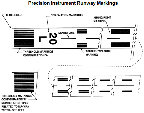
The purpose of runway designators are to identify and differentiate runways as seen from the approach end. These designators are the whole number to the nearest one tenth of the magnetic azimuth of the runway. Letters can be added to designate various parallel runways. These are used to differentiate between left ( L ), right ( R ), and center ( C ) runways. These markings are done in large white numbers (and letters where needed).
The purpose of the runway centerline marking is to give a visual center alignment reference on the runway. This provides guidance for takeoffs and landings. These lines are a sequence of uniformly spaced stripes and gaps.
The purpose of these markings are to identify the touchdown zone for aircraft landing on the runway. They also provide distance information in 500 foot increments. These are groups of 1, 2, and 3 rectangular bars in pairs about the runway centerline.
The purpose of these markings are to delineate the edges of the runway providing a contrast between the runway and the shoulder. They are a continuous white stripe located on each side of the runway.
These markings may be used with side stripes to identify pavement areas not intended for aircraft use. They are solid yellow stripes.
The purpose of these markings are to identify the beginning of the runway available for landing. These are a sequence of longitudinal stripes of uniform dimensions placed about the centerline. The number of stripes is related to runway width.
-
60 feet — 4 stripes
-
75 feet — 6 stripes
-
100 feet — 8 stripes
-
150 feet — 12 stripes
-
200 feet — 16 stripes
The threshold can be displaced or relocated based on circumstances. A displaced threshold is a point on the runway other than the designated beginning of the runway. This reduces the amount of runway available for landings, but can be used for taxiing, takeoff, and landing rollout. A displaced threshold is commonly used to address some obstruction on the approach path.
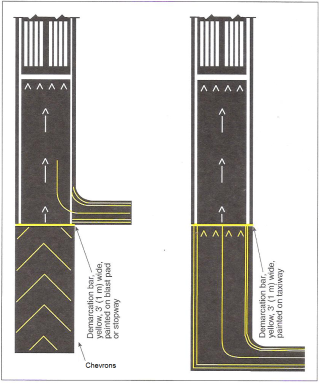
The threshold marking for a displaced threshold is a 10 foot wide threshold bar at the location of the displaced threshold. White arrow heads are located across the runway just prior to the threshold bar, and there are white arrows down the centerline between the runway and the displaced threshold.
There is a demarcation line that delineates the displaced threshold from a blast pad, stopway, or taxiway prior to the runway. This marking is 3 feet wide and yellow. There can also be chevrons which show areas aligned with the runway that are unusable for taxi, takeoff, and landing. These are large yellow arrows.
A relocated threshold can occur when there is construction or other activities which might require the threshold to be relocated. A NOTAM should be issued identifying the portion of the runway that is closed. Markings can vary as the duration of the relocation can vary. It is common practice to use a 10 foot wide white threshold bar across the runway. Runway lights between the old threshold and new threshold will not be illuminated. Runway markings in this area may or may not be showing.
A blast pad area is an area where a propeller or jet blast can dissipate without creating a hazard. A stopway is paved to provide space to decelerate/stop in the event of an aborted takeoff. These areas are marked with chevrons.
Taxiway Markings
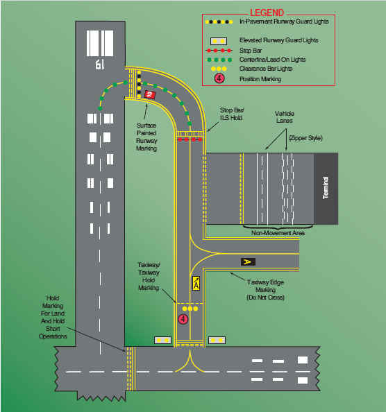
Taxiways have a number of markings which can aid the pilot in navigating on the airport surface. These markings provide clear indications of where the aircraft can safely operate, and areas to avoid (or operate with caution).
Taxiways generally have a centerline/runway holding position markings whenever they intersect a runway, have edge markings to separate the taxiway from areas not for aircraft use, and may have should and/or hold position markings for ILS critical areas and taxiway/taxiway intersections.
The centerline markings provide a visual cue to permit taxiing along a designated path. They are normally a single continuous yellow line that is 6 to 12 inches wide. At larger commercial airports there can be an enhanced centerline which is the same as a normal taxiway centerline but can include hold lines warning that a runway holding position is being approached and the aircraft should stop. These are a parallel line of dashes on either side of the normal taxiway centerline, and can extend up to a maximum of 150 feet prior to a runway holding position marking.
The edge markings define (as you might expect) the edge of the taxiway. This is more often included when the edge of the defined taxiway doesn’t line up with the edge of the paving. There are two types of edge markings, depending upon whether the aircraft is permitted to cross over the marking or not.
The first is a continuous yellow line which define the taxiway edge versus a shoulder or paved area beyond the edge which is not for use by aircraft. These are generally a continuous double yellow line with each line at least 6 inches wide, and 6 inches apart.
The second is a dashed yellow line which defines the taxiway edge when adjoining pavement is intended for aircraft use (such as an apron or ramp area). These are generally a broken double yellow line where the lines are 6 inches wide, 6 inches apart, and where the dashes are spaced so that they are 15 feet line and 25 feet apart.
These markings define a shoulder area that may be paved for some purpose (eg. to prevent erosion) but will not support an aircraft. These look the same as taxiway edge markings.
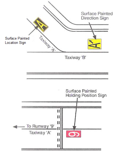
There are times when it isn’t convenient or even possible to provide direction signs at taxiway intersections. When this occurs markings on the taxiway itself can be used to supplement such signs. These are painted with a yellow background and black inscriptions. They are generally placed adjacent to the centerline with signs indicating left turns on the left side of the centerline and vice versa.
These markings identify aircraft location during low visibility operations. They are generally placed left of the taxiway centerline in the direction of taxiiing. They are a circle with an outer black ring, inner white ring, and a pink circle. When on dark pavements the white/black rings are reversed. The number corresponds with consecutive positions on the route.
These markings are used to indicate where an aircraft is supposed to stop when approaching a runway (hold on the solid sign). Identifying and complying with these markings are critical to avoid accidental runway incursions. They are denoted as four yellow lines across the taxiway, 2 solid and 2 dashed. These lines are spaced 6 to 12 inches apart across the width of the taxiway or runway. There are three areas where runway hold lines are encountered. They are taxiways, runways, and approach areas.
When found on a taxiway these markings indicate locations where aircraft are obligated to stop in the absence of a clearance from ATC to enter the runway environment. Always stop such that no portion of the aircraft extends beyond the hold markings. Never cross the hold markings without a clearance from ATC, and without clear separation from other aircraft at uncontrolled airports.
These are found infrequently, and are used only for LAHSO or taxiing operations. The aircraft must stop prior to the markings or exit prior to reaching the markings location. The markings are generally a sign with a white inscription on a red background next to hold markings on the surface.
These markings indicate a location where an aircraft should stop so that it doesn’t interfere with operations. These have multiple purposes. One is a hold marking for the ILS where an aircraft should stop to avoid entering the ILS critical area. These are generally 2 solid yellow lines spaced 2 feet apart joined by pairs of solid lines 10 feet apart across the taxiway.
These are installed on taxiways where ATC normally olds aircraft short of a taxiway intersection. They are a single dashed line extending across the width of the taxiway. If requested to hold short of a taxiway without markings, provide adequate clearance from the taxiway.
These are used to supplement the signs located at the holding position. They are normally used when the width of the holding position on the taxiway is greater than 200 feet. These markings are a white inscription on a red background, and are positioned left of the centerline on the holding side, just prior to the hold lines.
Other Markings
There are other various miscellaneous markings which can be found on the airport. They are not found at all airports, so may only infrequently be encountered. This makes it all the more important that they be studied and understood so that the pilot can safely operate at unfamiliar airports.
These are used to define a path for vehicle operations on or crossing areas also used by aircraft. These are white solid lines that delineate each edge and a dashed line separating lanes. In lieu of the solid lines "zipper markings" may be used to delineate the edges.
These markings identify a location where the pilot can perform a VOR check against a calibration signal. This is generally denoted as a painted circle with an arrow in the middle, with the arrow aligned toward the test facility. This circle also has a sign associated with it on the taxiway or apron showing the VOR station ID letters, the course used for the check, and any DME data (if appropriate). These are shown as black letters/numerals on a yellow background.
These marking delineate the movement areas (i.e. areas under ATC control) from any non-movement areas. These markings are 2 yellow lines, one solid and one dashed. These lines are 6 inches in width. The solid line is the non-movement area side, and the dashed line indicates the movement area side.
These markings and lighting denote a permanently closed runway, or taxiway. With respect to the lighting, the lights associated with the runway/taxiway will be disconnected. The runway threshold, designation, and touchdown markings will be obliterated. Yellow crosses are placed at each end of the runway and at 1,000 foot intervals.
These are used to provide a visual indication to pilots that a runway or taxiway is temporarily closed. Yellow crosses are placed on the runway at each end, or alternatively a raised yellow lighted cross may be used instead. A visual indication may not be present depending upon the reason for the closure, duration of the closure, configuration, and the hours of operation of an airport control tower. Check NOTAMs and the ATIS for information.
In the case of a closed taxiway they are treated as hazardous areas and are blockaded. No part of the aircraft may enter. As an alternative a yellow cross may be installed at each entrance to the taxiway.
Airport Signs
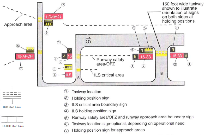
Signs installed on airport grounds fall into six distinct types. They are mandatory instruction, location, direction, destination, information, and runway distance remaining.
These signs denote entrances to runway or critical areas, or areas where aircraft are prohibited. These are signs with a red background and white inscriptions. Typical mandatory signs are :
- Runway Holding Position Sign
-
These signs are located at the hold position on taxiways intersecting runways, and on runways intersecting other runways. These signs state the designation of the intersecting runway.
- Runway Approach Area Holding Position Sign
-
These are used when necessary to hold aircraft on a taxiway in a runway approach/departure area so it doesn’t interfere with runway operations.
- ILS Critical Area Holding Position Sign
-
This indicates an area where an ILS is in use, and that it is necessary to hold at a location other than the runway hold markings. These signs will have the inscription "ILS" on them and will be located ajacent to the holding position markings on the taxiway.
- No Entry Sign
-
This sign indicates an area into which the aircraft may not enter. This is typically on a taxiway intended to operate in one direction, or at vehicle intersections which otherwise might be mistaken as a taxiway or movement area.
The purpose of these signs are to identify either a taxiway or a runway on which the aircraft is currently located. Other location signs provide a visual cue to assist in determining when an area has been exited.
- Taxiway Location Sign
-
These signs are placed along taxiways to indication the current location of the aircraft. These are signs with a black background and yellow inscriptions, and a yellow border.
- Runway Location Sign
-
These signs complement compass information, typically installed where the proximity of runways to one another could cause confusion as to which runway the pilot is on. These are also signs with a black background and yellow inscriptions.
- Runway Boundary Sign
-
These provide a visual cue to use a s a guide in deciding when the aircraft is "clear of the runway". These signs are adjacent to the hold markings on the pavement, and are visible when exiting the runway. They are signs with a yellow background with a black inscription depicting the hold markings.
- ILS Critical Area Boundary Sign
-
These signs provide a visual cue in deciding when clear of the ILS critical area. These are placed adjacent to ILS hold markings and can be seen when leaving the ILS critical area. They are a yellow background with black markings depicting the ILS hold markings.
- Direction Signs
-
These signs identify the designations of intersecting taxiways leading out of an intersection. Designations and their arrows are arranged clockwise from the 1st taxiway on the pilot’s left. These are signs with a yellow background with black inscriptions and an arrow indicating the turn direction.
- Destination Signs
-
These signs show a particular destination on the airport surface. These signs can depict destinations for runways, aprons, terminals, military areas, civil aviation areas, cargo areas, international areas, and FBOs. These signs have a yellow background and a black inscription indicating the destination on the airport.
- Information Signs
-
These are used to provide a pilot with information on things such as areas the tower can’t see, radio frequencies, and noise abatement procedures. These are also signs with a yellow background and a black inscription.
- Runway Distance Remaining Signs
-
These signs are positioned along the side of the runway to inform the pilot of the distance remaining on the runway. The number on the sign indicates the thousands of feet of runway remaining. These signs have a black background with a white numeral inscription.
Airport Lighting and Other Airport Visual Aids
There are various lights used to communicate information to pilots positioned on the airport grounds. These are used both during surface operations as well as during landings.
The approach lights are used as the primary means of transitioning from instrument conditions to visual conditions for landing. These are a configuration of lights starting at the landing threshold and extending into the approach area.
These lights provide visual descent guidance information during an approach. They are visible from 3 to 5 miles out during the day, and up to 20 or more miles at night. They provide save obstruction clearance with ±10° of the centerline and within 4 NM of from the threshold.
One type of lights are the Visual Approach Slope Indicator (VASI) lights. These lights come in a number of configurations. They can come with 2, 4, 6, 12, or 16 lights arranged in pairs. They are arranged as near, middle, and far bars (with the middle providing another glide path for higher cockpits). VASIs of 2, 4, or 6 lights are positioned on one side of the runway (usually on the left), and VASIs consisting of 12 or 16 light units are located on both sides of the runway. The two-bar VASI provides one visual glide path, normally set at 3°, where the three-bar VASI provides two visual glide paths. The lower glid path is provided by the near and middle bars and is normally set to 3° (though some locations may have a 4.5° glide path for proper obstacle clearance). The upper glide path is provided by the middle and far bars and is normally set 1/4° higher.
Each unit projects light with an upper white segment and a lower red segment. The lights are arranged so that the pilot will see combinations of the various lights.
Another version of the visual approach lighting system is the Precision Approach Path Indicator (PAPI). These are also arranged to give the pilot a visual indication of the approach path. The lights are similar to the VASI but are either 2 or 4 light systems. They come in two different styles.
One PAPI style is the tri-color system, which is normally a single unit projecting a 3-color visual approach path into the final approach area. The glide path indicators are : below glideslope — RED, above glideslope - AMBER, and on glideslope - GREEN. The useful range is 1/2 to 1 mile during the day, and up to 5 miles at night.
The other PAPI style is the pulsating system, which is normally a single unit projecting a 2-color visual approach path into the final approach area. The glide path indicators are : slightly below glideslope - Steady RED, below glideslope - pulsating RED, on glideslope - WHITE, slightly above glideslope - pulsating WHITE, and above glideslope - _Faster pulsating WHITE.
These lights are installed at the end of the runway to provide a rapid and positive identification of the approach end of a runway. These are a pair of synchronized flashing lights located on each side of the runway threshold. They are effective for identification of a runway with a preponderance of other lighting in the area, identification of a runway which may lack good contrast with the surrounding area, or identification of a runway during reduced visibility.
The outline of the edges of runways during periods of darkness or in restricted visibility conditions. These lights are classified based on the intensity or brightness they are capable of producing. These categories are : high intensity (HIRL), medium intensity (MIRL), and low intensity (LIRL).
These lights are configured in different colors. The runway edge lights are generally white, though turn yellow during the last 2,000 feet or half of the runway, whichever is shorter. Red is emitted toward the runway to indicate the end of the runway for a departing aircraft, and green is emitted outward from the runway end to indicate the threshold to a landing aircraft.
These lights serve a number of different purposes. This includes centerline lighting, touchdown zone lighting, taxiway center lead-off lighting, taxiway center lead-on lighting, and land and hold short lighting,
- Centerline Lights
-
These lights are installed on some precision runways to facilitate landing under adverse conditions. They are located along the runway centerline and are spaced at 50 foot intervals. From the landing threshold the lights are white until the last 3,000 feet of the runway. White lights begin to alternate with red for 2,000 feet, and the last 1,000 feet of travel all lights are red.
- Touchdown Zone Lights
-
These lights are installed on some precision runways to indicate the touchdown zone under adverse visibility conditions. These are two rows of transverse light bars disposed symmetrically about the runway centerline. Steady burning white lights starting 100 feet beyond the landing threshold and extending to 3,000 beyond the landing threshold or to the midpoint of the runway whichever is less.
- Taxiway Center Lead On/Off Lights
-
These lights (if installed) provide visual guidance to an aircraft exiting the runway. They can be color coded to warn that the aircraft is in the runway environment or the ILS critical area, whichever is more restrictive. These lights alternate between green and yellow lights from the runway centerline to 1 light position beyond the runway hold position or ILS critical area hold position. These lights are bi-directional with one side emitting light for the lead-on function, and the other side emitting light for the lead-off function.
- Land and Hold Short Lights
-
These lights (if installed) are used to indicate the hold short point on certain runways which are approved for LAHSO. Where installed these lights will be on whenever LASHO is in effect and off when not. These are a row of pulsing white lights installed across the runway at the hold short point.
The lighting systems are controlled in various ways, generally depending upon whether the airport is controlled or uncontrolled. At an airport with a tower the approach lights are controlled by either the tower or FSS. The pilot can request the intensity desired.
At uncontrolled airports the lights may (if the airport supports the function) be controlled by the pilot by use of microphone "clicks". Where this is available all lighting at the airport are controlled on the same frequency. The CTAF is commonly used for controlling the lights, but other frequencies can be used. Check the Chart Supplement and the standard instrument approach procedures publications. The frequency used is not identified on the sectional chart.
The general rule is that clicking the microphone 7 times within 5 seconds gives the highest intensity setting, 5 times within 5 seconds give a medium or lower intensity setting, and 3 times within 5 seconds gives the lowest intensity setting.
These lights are installed at airports to allow a pilot to identify visually the location of an airport from a distance at night, or in low visibility conditions. These lights are oriented vertically so as to make them most effectively visible from about 1° to 10° above the horizon. However, they can often be seen outside this spread. The beacon rotates at a constant speed such that it produces 24 to 30 flashes per minute from airports, landmarks, or points on federal airways, and 30-45 flashes per minute for heliports.
There are a number of different colors and color combinations used for beacons. The list of colors and combinations are listed here.
| White/Green |
Indicates a lighted land airport |
| Green (alone) |
Indicates a lighted land airport also |
| White/Yellow |
Indicates a lighted water airport |
| Yellow (alone) |
Indicates a lighted water airport also |
| Green/Yellow/White |
Indicates a lighted heliport |
Military airports are yet again different, using two quick white flashes followed by a single green flash to indicate their location.
If a beacon is being operated during the day in class B, C, D, and E surface areas it can indicate that ground visibility is less than 3 miles and/or the ceiling is less than 1,000 feet. However, don’t rely solely on the airport beacon to indicate if weather conditions are IFR or VFR because there is no regulatory requirement for daylight beacon operation.
Taxiway Lights
There are a number of lights associated with taxiways that also guide the pilot operating on the airport surface.
- Taxiway Edge Lights
-
These lights outline the edges of taxiways during periods of darkness or restricted visibility. They are generally blue lights.
- Taxiway Centerline Lights
-
These lights are used to facilitate the identification of the taxiway centerline during periods of darkness or restricted visibility. These are generally steady green lights along the centerline.
- Clearance Bar Lights
-
These lights are used to increase the conspicuousness of the holding position in low visibility conditions. These may also be installed to indicate the location of an intersecting taxiway during darkness. These are generally three in-pavement steady burning yellow lights.
- Runway Guard Lights
-
These lights are intended to increase the conspicuousness of taxiway and runway intersections. These will either be a pair of elevated flashing yellow lights on either side of the taxiway, or a row of in-pavement yellow lights across the entire taxiway. These will be positioned at the runway hold markings.
- Stop Bar Lights
-
These lights are to confirm ATC clearances to enter or cross the active runway in low visibility conditions. These are a row of red, unidirectional, steady burning in-pavement lights installed across the entire taxiway in each side. Following an ATC clearance these lights are turned off and the lead-on lights are turned on. NEVER cross ared illuminated stop bar even if you have received ATC clearance. If after crossing the stop bar the lead-on lights extinguish, hold positon and contact ATC for instructions.
Common Errors
-
Failure to comply with airport, runway, taxiway signs and markings
-
Failure to comply with airport, runway and taxiway lighting
-
Failure to use proper runway incursion avoidance procedures
Conclusion
It is important to understand the meaning of the airport, runway and taxiway signs, markings, and lighting for safety as well as to avoid runway incursions. If you are confused or have a question, do not proceed. Stop the aircraft and ask ATC.
ACS Requirements
To determine that the applicant:
-
Exhibits instructional knowledge of the elements of airport, runway and taxiway signs, markings, and lighting by describing:
-
Identification and proper interpretation of airport, runway and taxiway signs and markings, with emphasis on runway incursion avoidance.
-
Identification and proper interpretation of airport, runway and taxiway lighting, with emphasis on runway incursion avoidance.
-
-
Exhibits instructional knowledge of common errors related to airport, runway and taxiway signs, markings, and lighting by describing:
-
Failure to comply with airport, runway and taxiway signs and markings.
-
Failure to comply with airport, runway and taxiway lighting.
-
Failure to use proper runway incursion avoidance procedures.
-
-
Demonstrates and simultaneously explains airport, runway and taxiway signs, markings, and lighting from an instructional standpoint.
-
Analyzes and corrects simulated common errors related to airport, runway and taxiway signs, markings, and lighting.