Lesson Overview
The student should develop knowledge of the elements related to the {aircraft-type} systems and their operation as required in the ACS/PTS.
References : Airplane Flying Handbook (FAA-H-8083-3C), Pilot’s Handbook of Aeronautical Knowledge (FAA-H-8083-25C), POH/AFM
| Key Elements |
|
| Elements |
|
| Schedule |
|
| Equipment |
|
| IP Actions |
|
| SP Actions |
|
| Completion Standards |
The student understands the operation of the systems in the {aircraft-type} aircraft. |
Instructor Notes
| Attention |
The inner workings of the airplane; to develop a better understanding of what is what, and what is where. |
| Overview |
Review Objectives and Elements/Key ideas |
| What |
The main systems found on the DA20. This includes the primary flight controls and trim, flaps, powerplant, propeller, landing gear, fuel, oil and hydraulic systems, electrical and avionics systems, flight instruments and the environmental system. |
| Why |
Understanding how the airplane works internally will allow for better troubleshooting and problem identification. The pilot will have a better understanding of the airplane as a whole. |
Lesson Details
Primary Flight Controls and Trim
The primary flight controls are all aluminum semi-monocoque, generally assembled with rivets. The control surfaces are manually operated through cables and mechanical linkage using a control wheel for the ailerons and elevator, and rudder/brake pedals for the rudder.
- Ailerons
-
These are conventional piano-hinge attached control surfaces. The ailerons are constructed of a forward spar containing balance weights, formed sheet metal ribs and "V" type corrugated aluminum skin joined together at the trailing edge.
- Elevator
-
Construction of the elevator consists of formed leading edge skins, a forward spar, aft channel, ribs, torque tube and bellcrank, left upper and lower "V" type corrugated skins, and right upper and lower "V" type corrugated skins incorporating a trailing edge cutout for the trim tab. The elevator tip leading edge extensions incorporate balance weights. The elevator trim tab consists of a spar, rib, and upper and lower "V" type corrugated skins.
- Rudder
-
The rudder is constructed of a formed leading edge skin and spar with attached hinge brackets and ribs, a center spar, a wrap around skin, and a ground adjustable trim tab at the base of the trailing edge. The top of the rudder incorporates a leading edge extension which contains a balance weight.
Control Locks
A control lock is provided to lock the aileron and elevator control surfaces to prevent damage to these systems by wind buffeting while the airplane is parked. The lock consists of a shaped steel rod and flag. The flag identifies the control lock and cautions about its removal before starting the engine. To install the control lock, align the hole in the top of the pilot’s control wheel shaft with the hole in the top of the shaft collar on the instrument panel and insert the rod into the aligned holes. Installation of the lock will secure the ailerons in a neutral position and the elevators in a slightly trailing edge down position. Proper installation of the lock will place the flag over the ignition switch. In areas where high or gusty winds occur, a control surface lock should be installed over the vertical stabilizer and rudder. The control lock and any other type of locking device should be removed prior to starting the engine.
Flaps
The flaps are constructed basically the same as the ailerons, with the exception of the balance weights (which are not included in the construction of the flaps) and the addition of a formed sheet metal leading edge section.
Powerplant and Propeller
The engine is a fuel injected Textron Lycoming I0-360-L2A. It is a horizontally opposed 4-cylinder engine and generates 180 BHP at 2700 RPM. The engine is air cooled and the propeller is driven directly from the crankshaft.
The propeller is a 76 inch McCauley 1A170E/JHA7660 fixed pitch prop.
The engine is controlled by a throttle knob, as well as a mixture control knob. These are mounted on the panel between the two pilot’s seating positions. The alternate air is a spring-loaded door and is not manually controlled by the pilot.
Landing Gear
The landing gear is of the tricycle type, with a steerable nose wheel and two main wheels. Wheel fairings are standard equipment for both the main and nose wheels. Shock absorption is provided by the tubular spring steel main landing gear struts and the air/oil nose gear shock strut. Each main gear wheel is equipped with a hydraulically actuated disc type brake on the inboard side of each wheel.
Fuel, Oil, and Hydraulic
Allowed fuels for the engine are 100LL grade aviation fuel (blue) and 100 grade aviation fuel (green). Fuel is stored in two aluminum fuel tanks, one in each of the forward inboard portion of each wing.
The maximum fuel capacity is 56 gallons (53 usable), and the maximum oil capacity is 8 quarts. The fuel system consists of two vented wing mounted fuel tanks, a three-position selector valve, auxiliary fuel pump, fuel shutoff valve, fuel strainer, engine driven fuel pump, fuel/air control unit, fuel distribution valve and fuel injection nozzles.
Fuel flows by gravity from the two wing tanks to a three-position selector valve, labeled BOTH, RIGHT and LEFT and on to the reservoir tank. From the reservoir tank fuel flows through the auxiliary fuel pump, past the fuel shutoff valve, through the fuel strainer to an engine driven fuel pump. Closing the fuel shutoff valve will cause the engine to stop within a short period of time.
From the engine-driven fuel pump, fuel is delivered to the fuel/air control unit, where it is metered and directed to a fuel distribution valve (manifold) which distributes it to each cylinder. Fuel flow into each cylinder is continuous, and flow rate is determined by the amount of air passing through the fuel/air control unit.
Fuel quantity is measured by two float type fuel quantity transmitters (one in each tank) and indicated by an electrically operated fuel quantity indicator on the left side of the instrument panel. The gauges are marked in gallons of fuel. An empty tank is indicated by a red line and the number 0. When an indicator shows an empty tank, approximately 1.5 gallons remain in each tank as unusable fuel.
MIL-L-22851 or SAE J1899 Aviation Grade ashless dispersant oil should be used after the engine brake-in period. The oil delivery system is a high pressure wet sump lubrication system. The oil is stored in a pan (or sump) which is part of the bottom of the engine. The oil pump is a mechanical engine driven pump, and the oil quantity should be between 4 and 6 quarts, with the maximum amount of oil being 8 quarts.
The only hydraulics in the aircraft are the brakes, and the nosewheel strut. The brakes used MIL-H-5606 brake fluid, as does the nosewheel shock strut.
Electrical
The airplane is equipped with a 28-volt, direct current electrical system. The system is powered by a belt driven, 60-amp alternator and a 24-volt battery, located on the left forward side of the firewall. Power is supplied to most general electrical circuits through a split primary bus bar, with an essential bus wired between the two primaries to provide power for the master switch, annunciator circuits and interior lighting. Each primary bus bar is also connected to an avionics bus bar via a single avionics master switch. The primary buses are on anytime the master switch is turned on, and are not affected by starter or external power usage. The avionics buses are on when the master switch and avionics master switch are in the ON position.
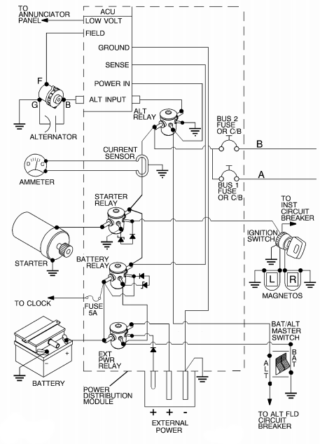
The airplane uses a power distribution module (J-Box), located on the left forward side of the firewall, to house all relays used throughout the airplane electrical system. In addition, the alternator control unit and the external power connector are housed within the module.
The master switch is a split-rocker type switch labeled MASTER and is ON in the up position and OFF in the down position. The right half of the switch, labeled BAT, controls the battery power to the airplane. The left half, labeled ALT, controls the alternator.
The ammeter/vacuum gage is located on the lower left side of the instrument panel. It indicates the amount of current, in amperes, from the alternator to the battery or from the battery to the airplane electrical system. When the engine is operating and the master switch is turned on, the ammeter indicates the charging rate applied to the battery.
Avionics
The avionics are installed in the panel, with the bulk of the radio and navigation equipment placed in the center of the instrument panel. Since it is common to change and upgrade the avionics over time, the operations manuals for the specific equipment installed in a given aircraft should be consulted for systems operations information.
Pitot/Static, Vacuum Pressure, and Associated Flight Instruments
The pitot pressure is measured from a calibrated probe installed underneath the left wing. No pitot installation is perfect, though the manufacturer strives to have the errors be minimal over the span of normal airspeeds used in regular flight. Static pressure is measured by a port on the side of the aircraft. The combined pressures (pitot and static) drive a number of instruments.
The airspeed indicator is driven by both pitot and static pressure. The airspeed is derived from the difference between the static/ambient air pressure and the ram air pressure from the pitot.
The altimeter derives the altitude from the static/ambient air pressure only. The mean seal level (MSL) altitude is set by an adjustment made on the instrument for the local barometric pressure. This permits all aircraft to measure altitude against a common reference point.
This is another instrument which uses only static/ambient pressure. It derives the rate of climb/descent based on the change in static/ambient pressure over time.
The vacuum pressure is generated by an engine driven vacuum pump. This pump provides suction to various instruments, primarily the heading indicator and the attitude indicator. The vacuum draws air through these instruments which streams over the vanes of a rotating gyroscope. Gyroscopic properties of rigidity in space cause these instruments to be able to indicate attitude and headings as the aircraft pitches, turns, and maneuvers.
Commonly the only electrically driven instrument is the turn coordinator. It is also an instrument which uses gyroscopic properties to derive its indications, but does so with an electric motor to provide redundancy in the event of a vacuum pump failure.
Environmental
Environmental controls in the {aircraft-type} are fairly rudimentary. The aircraft has fresh air vents which can direct ram air into the cabin. There is the ability to route air over a heat exchanger (aka: heat muff) on the engine exhaust to create warm air that can be introduced into the cabin. Finally, there is the ability to direct air toward the windshield to defrost (or even deice, if the ice is very minimal).
Conclusion
A thorough understanding of the airplane’s systems makes a safer, smarter pilot.
ACS Requirements
To determine that the applicant exhibits instructional knowledge of the elements related to the operation of systems, as applicable to the airplane used for the practical test, by describing the following systems:
-
Primary and secondary flight controls
-
Trim
-
Powerplant and propeller
-
Landing gear
-
Fuel, oil, and hydraulic
-
Electrical
-
Avionics including autopilot
-
Pitot static, vacuum/pressure and associated instruments
-
Environmental