Lesson Overview
The student should develop knowledge of the elements related to the navigation systems and radar services provided by ATC as required in the ACS/PTS.
References : Airplane Flying Handbook (FAA-H-8083-3C), Pilot’s Handbook of Aeronautical Knowledge (Chapter(s) : 15), Instrument Flying Handbook (FAA-H-8083-15B), Airmans Information Manual
| Key Elements |
|
| Elements |
|
| Schedule |
|
| Equipment |
|
| IP Actions |
|
| SP Actions |
|
| Completion Standards |
The student will understand the operation of different navigation systems as well as their use in the airplane. The student also will understand and be able to utilize the radar services provided by ATC. |
Instructor Notes
| Attention |
Understanding this will greatly decrease your chances of getting lost and provide more services for use. |
| Overview |
Review Objectives and Elements/Key ideas |
| What |
This lesson discusses the different navigation systems in use as well as radar services provided by ATC when in radar coverage and with established communication. |
| Why |
It is important to understand how the navigation systems function in order to properly use them. It also is important to know the services provided by ATC to pilots. |
Lesson Details
The general concepts of navigation were discussed in the Navigation and Flight Planning lesson plan. with radio navigation being one of the techniques included. This lesson goes into more detail about the available navigation systems and radar services. There are a small number of different navigation systems deployed in the United States. They include VOR/VORTAC, satellite based navigation (GPS), and radar services. Certain older systems have either been decommissioned, or are being reduced in their usage. The LORAN-C system was decommissioned in the US and Canada as of 2010. The system of Non-Directional Beacons (NDBs) is being slowly phased out, so they are no longer considered a primary radio navigation system in the United States.
Very High Frequency Omnidirectional Range (VOR/VORTAC)
The VOR/VORTAC has been a mainstay of cross-country navigation for decades, and is still in use today. There are three types of VOR deployments in the US.
| VOR |
The VOR by itself, providing magnetic bearing information to and from the station |
| VOR/DME |
When Distance Measuring Equipment (DME) is also installed with the VOR. |
| VORTAC |
When military tactical air navigation (TACAN) equipment is installed with the VOR. DME is always an integral part of a VORTAC. |
The VOR comprises a VHF radio transmitting ground station that projects straight line courses (radials) form the station in all directions (thus the "omni" in the name). The distance the radials are projected depend upon the power output of the transmitter. These radials are projected referenced to magnetic north thus a radial is defined as a line of magnetic bearing extending out from the VOR station. The accuracy of course alignment with radials is considered to be excellent, in the range of plus or minus one degree.
These ground stations transmit in the RF band of 108.0 to 117.95, and because the transmission is VHF it is limited to line-of-sight. This means that the ability to receive the VOR signal varies in proportion to the altitude of the receiving antenna.
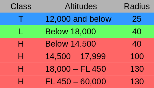
VORs are classed according to operational use in three classes, with varying normal useful ranges. These classes are: "T" (terminal), "L" (low altitude), and "H" (high altitude).
The best assurance for maintaining an accurate VOR receiver is periodic checks and calibrations of the receiver. However, regular VOR checks are not a requirement for VFR flight (but are required for IFR). There are various means of checking the VOR accuracy, with checkpoints listed in the Chart Supplement. Four ways to check the VOR are :
-
FAA VOR Test Facility (VOT)
-
Certified Airborne Checkpoints
-
Certified Ground Checkpoints located on airport surface
-
Dual VOR check
These checks verify that the VOR radials the eqiupment receives are aligned with the radials that the stations transmit. IFR tolerances required are plus or minus four degrees for ground checks, and plus or minus six degrees for airborne checks.
VOR Usage
The VOR is a radio receiver, and is tuned to the frequency of the VOR station to be used. The station can be identified by a Morse code identifier, or a voice telling the name of the station. If, however, the VOR is out of service the identifier is removed and the absence of an identifier means that the station should not be used for navigation. VOR receivers can also have an alarm flag to indicate when the signal strength is too weak (because the aircraft is too low, or two far away, or is out of the line-of-sight of the station) and should not be used for navigation. Finally, even if a Morse code is detected it should be confirmed that the VOR is not broadcasting the Morse for "test", as this is sometimes also done. If in testing a VOR should not, obviously, be used for navigation.
There are two components required for VOR radio navigation. These are the ground transmitter, and the airborne receiver. The ground station is at a specific known location on the surface, and it transmits on an assigned frequency. The receiver in the aircraft can tune that frequency and has a means to display information from that signal. This instrument is traditionally a "VOR head" (though these days electronic indicators are becoming more common) which has an omni bearing selector (OBS), referred to as a "course selector", a course deviation indicator (CDI) needle, and a To/From indicator. The source selector is an azimuth dial that is rotated to select a radial (and can be used to identify the magnetic course to/from the station if desired). When the OBS is rotated the CDI moves to show the position of the radial relative to the plane.
When the OBS is rotated such that the CDI is centered, this indicates the radial (magnetic course FROM the station) or its reciprocal (magnetic course TO the station). The CDI will also move right/left if the airplane is not on the selected radial
The To/From indicator indicates whether the selected radial denotes the course TO the station, or the bearing FROM the station. If To is shown and the indicated course is flown, the aircraft will travel to the station. If From is shown and the indicated course is flown, the aircraft will fly away from the station on that magnetic course.
Tracking a VOR
To track to a VOR first tune the station and verify it is the desired VOR by listening to the station identifier. Rotate the OBS to center the CDI with a "To" indication, and turn to the heading indicated on the OBS azimuth dial. This will track straight to the VOR in a no wind situation.
However, if there is a crosswind and that indicated heading is maintained the aircraft will drift off course. If the wind is from the right, the aircraft will drift left of course (and vice versa). To return to the desired radial the aircraft will have to be turned back toward the course and this correction held until the CDI re-centers. To correct for this drift and maintain the desired course the aircraft will need to crab into the wind just the right amount to counteract the crosswind. This will be a trial-and-error exercise with (hopefully) the corrections needed to maintain course being identified with a few iterations. If you happen to have a GPS the aircraft track can be shown and can confirm that the aircraft is on the desired course.
Upon arriving at, and then passing, a VOR station the "TO" indication will flip to a "FROM" indication. Generally flying away from a VOR will follow the same process. If a new course is desired at the VOR (they are often used as turn points) then a new course should be entered in the OBS.
It should be noted that if you are flying to a VOR with a "FROM" indication, or away from the VOR with a "TO" indication, that it works fine with the provision that the CDI is in a reverse sensing situation. Therefore, if the needle moves right you are actually right of the course, and vice versa if the needle moves left. This reverse sensing must be accounted for or confusion will occur.
VOR Tips
There are a number of things to remember, or actions to take, when navigating via VOR. One is to always positively identify the station by its code or voice ID. When tracking to a station determine the inbound course and use it. Don’t succumb to the temptation to just twist the OBS to re-center the VOR. If done too much the aircraft will describe a spiral path to the station until the winds are directly in line with the course being flown, which is very sloppy flying. When flying TO a station always use a TO indication, and the reverse when flying away, thus avoiding the possible confusion of reverse sensing.
| Includie George’s "how to read a VOR" method here. George?? |
Satellite Based Navigation (GPS)
Over the last few decades GPS technology has started to pervade our live, including our flying. Satellite based navigation have a number of components which include the GPS satellite system itself, the Wide Area Augmentation System (WAAS), and the Local Area Augmentation System (LASS).
The broader GPS system is composed of three major elements. The Space Segment, the Control Segment, and the User Segment.
- Space Segment
-
This segment is currently composed of 31 satellites each approximately 11,000 nm above the earth. The US is committed to maintain 24 operational satellites 95% of the time arranged so that at any time 5 are in view to any receiver (with 4 being the minimum necessary for operation). Each satellite orbits the earth in approximately 12 hours and are equipped with extremely stable atomic clocks each transmitting a unique code/nav message. These satellites broadcast in the UHF frequency range which reduces the impact of weather on the signals. These signals are line-of-sight, so a satellite must be above the horizon to be "visible" to the GPS receiver.
- Control Segment
-
This segment consists of a master control station, five monitoring stations, and three ground antennas. The monitoring stations and ground antennas are distributed around the globe to allow continual monitoring and communications with the satellites. Updates and corrections to the nav message broadcast are uplinked as the satellites pass over the ground antennas.
- User Segment
-
This consists of all compoents associated with the GpS receiver. These can range from simple portable hand-held receivers to those permanently mounted in the aircraft. The receiver uses the signals from the satellites to calculate position, velocity, and precise timing to the user.
To solve for a location the GPS receiver uses the calculated distance and position information from the satellite from at least four satellites to yield a 3-D fix. This fix includes latitude, longitude, and altitude. VFR navigation with GPS can be a simple as selecting a destination and tracking the course (i.e. the Magenta Line). With GPS the course deviation is linear so that there is no increase in sensitivity when approaching a waypoint. It can be extremely tempting to rely exclusively on GPS, but never rely on one means of navigation.
Achieving Higher Precision
The Wide Area Augmentation System (WAAS) and Local Area Augmentation System (LAAS) were deployed to achieve a higher degree of position precision for the GPS system. This improves the position calculation enough such that the GPS can be used for precision approaches. In the worst case WAAS precision is accurate to 25 feet 95% of the time. Like GPS the WAAS includes Space, Control, and User segments.
The LAAS is very similar to WAAS, but relies more on ground stations for signal correction and improvement. However, it is considered to be less cost effective than WAAS, but is also considered to be capable of handling Category III approaches.
Radar Services and Procedures
Finally, it is possible for ATC facilities to provide a variety of navigation services to participating VFR aircraft on a workload permitting basis. To use these facilities you must be able to establish two-way communications with ATC, be within radar coverage of the facility, and be radar identified. Services that can be provided include :
-
VFR radar traffic advisory service (Flight Following) and safety alerts
-
Vectoring (when requested)
-
Terminal Radar Programs (TRSA) – To separate all participating VFR aircraft and IFR traffic
-
Radar assistance to lost aircraft
-
Class C services include separation between IFR/VFR and sequencing of VFR traffic to the airport
-
Class B services include separation based on IFR, VFR and/or weight and sequencing VFR arrivals
Conclusion
When navigating with a VOR and you wish to head toward the station ensure the flag indicates “TO” and follow the indicated heading. When it is necessary to track away from the station, ensure the flag indicates “FROM” and follow the heading indicated. Failing to do this could result in reverse sensing (not applicable to an HSI). GPS is a satellite based system that used for navigation. WAAS and LAAS are also satellite based navigation systems but they augment the GPS system with ground based stations allowing for more precise location information as well as vertical guidance. The radar services provided by ATC can be very helpful in almost any flight.
ACS Requirements
To determine that the applicant exhibits instructional knowledge of the elements related to navigation systems and radar service by describing:
-
One ground-based navigational aid (VOR/VORTAC, NDB, and DME).
-
Satellite-based navigation aids.
-
Radar service and procedures.
-
Global positioning system (GPS).