Lesson Overview
The student should develop knowledge of the elements related to navigation and flight planning as required in the different applicable tasks in the ACS.
References : Airplane Flying Handbook (FAA-H-8083-3C), Pilot’s Handbook of Aeronautical Knowledge (FAA-H-8083-25C)
| Key Elements |
|
| Elements |
|
| Schedule |
|
| Equipment |
|
| IP Actions |
|
| SP Actions |
|
| Completion Standards |
The student can properly and confidently plan and execute a cross country flight to any chosen destination. The student also understands the procedures for diversions and lost situations. |
Instructor Notes
| Attention |
This is what leads into using everything you have learned so far and flying yourself somewhere! |
| Overview |
Review Objectives and Elements/Key ideas |
| What |
Navigation and flight planning is the process of planning and executing cross country flights |
| Why |
This information will make planning flights easier and more organized and provide procedures for different situations that may arise during the flight. |
Lesson Details
Navigation and flight planning is an involved and detailed subject with numerous terms. These should first be defined before use in the subsequent sections.
Terms and Definitions
-
True Course – The direction of flight as measured on a chart clockwise from true North
-
True Heading – The direction the longitudinal axis of the airplane points with respect to true North
-
True heading equals true course plus or minus any wind correction angle
-
-
Magnetic Course – True course corrected for magnetic variation
-
Magnetic Heading – Magnetic Course corrected for wind (direction and speed)
-
Compass Heading – Aircraft heading read from the compass
-
Derived by applying correction factors for variation, deviation, and wind to your true course
-
-
Deviation – Compass error due to magnetic disturbances from electrical/metal parts in the plane
-
The correction for this is displayed on a compass correction card near the magnetic compass
-
-
Variation – The angular difference between true north and magnetic north; isogonic lines on charts
-
Standard Pressure – 29.92” Hg (at sea level)
-
Standard Temperature – 15o C/59oF (at sea level)
-
Indicated Alt – Altitude read directly from the altimeter after it’s set to the current altimeter setting
-
Pressure Alt – Height above the standard pressure level of 29.92 in Hg -
-
Obtained by setting 29.92 in the barometric pressure window and reading the altimeter
-
-
Density Alt – Pressure altitude corrected for nonstandard temperatures -
-
The equation above is not exact.
-
Directly related to an aircraft’s takeoff, climb, and landing performance
-
-
True Altitude – The true vertical distance of the aircraft above mean sea level (MSL)
-
Airport, terrain, and obstacle elevations found on aeronautical charts are true altitudes.
-
-
Absolute Altitude – The vertical distance of the aircraft above the surface of the earth (AGL)
-
Indicated (IAS) – The speed of an aircraft as shown on the airspeed Indicator
-
Calibrated (CAS) – Indicated airspeed of an aircraft, corrected for installation and instrument errors
-
Equivalent (EAS) – CAS corrected for adiabatic compressible flow for the particular altitude
-
True (TAS) – The speed at which an aircraft is moving relative to the surrounding air
-
Equal to CAS corrected for density altitude
-
-
Groundspeed (GS) – The speed of the aircraft in relation to the ground
-
Equal to TAS corrected for wind(tailwind/headwind)
-
Aeronautical Charts
The maps used by the aviation community are not called maps, but are normally referred to as charts. These are graphical depictions which provide pilots with information used to track position and greatly enhance safety.
The VFR pilot mainly uses two different charts : the Sectional Chart and the VFR Terminal Area Chart. The sectional chart provides information regarding airports, navaids, airspace, and topography. The scale is 1:500,000 (1" == 6.86NM) and is revised semiannually. The VFR Terminal Area chart are intended to help when flying in or near Class B airspace. They provide a more detailed depiction of topographical information. The scale is 1:250,000 (1" == 3.43NM) and are also revised semiannually.
Both charts display topographical information with surface elevations and a large number of visual checkpoints. These can include roads, railroads, power lines, aerial cables, and may different landmarks. These charts also include visual and radio aids to navigation, airports, controlled airspace, restricted areas, obstructions, and related data.
It is critical to check the publication date for charts to insure current information. Anything can change, including radio frequencies, added obstructions, temporary or permanent closing of certain runways and airports, and other temporary or permanent hazards to flight.
Navigation Techniques
There are various approaches to navigation, starting with the most basic dead reckoning and pilotage to GPS direct. These approaches are detailed in the next sections.
Pilotage and Dead Reckoning
Pilotage is navigation by reference to landmarks or checkpoints. This is a method that can be used on any course with adequate checkpoints, but it is most commonly used with dead reckoning and VFR radio navigation. When visibility is low, or there are few identifiable checkpoints, this technique becomes difficult.
Checkpoints selected should be prominent features along the route of flight. This can include roads, rivers, railroad tracks, lakes, towns, and power lines. It should be remembered that new roads and other features are being constructed (and sometimes removed) regularly, so charts may be out of date with respect to reality.
Good selection of checkpoints can make a difference. Select features that will make useful boundaries on both sides of the course. This helps maintain the desired course. Never count on a single checkpoint, and if one is missed maintain heading and look for the next. If a turn is planned, make the turn based on time if a checkpoint is not in sight, and don’t just continue on heading blindly.
Dead reckoning is navigation solely by calculations based on time, speed, distance, and direction. The results provided by this when adjusted for wind speed are heading and ground speed. The calculated heading will guide the plane along the desired course, and the groundspeed will establish the time expected over each given checkpoint (in a perfect world). Except for flight over featureless terrain (such as water) dead reckoning is normally used in conjunction with pilotage. The heading and groundspeed are constantly checked against pilotage, and adjusted as needed. Radio navigation can also be included, where available, so that further precision can be achieved.
Radio Navigation
This is navigation by use of radio signals to denote the desired flight path. There are traditionally four different radio systems used for cross country navigation: VOR, NDB, LORAN-C, and GPS. The NDB system is being phased out, and the LORAN-C system has been shut down entirely. At this time GPS and VOR are the predominant cross-country radio navigation systems in use.
GPS Navigation
Over recent years GPS has gained in popularity, and the magenta line has become the primary mechanism used to fly a desired course. Before a flight is undetaken waypoints are entered into the GPS, and these waypoints can be found on a VFR sectional and terminal charts. The GPS will provide information similar to a flight navigation log, and may update details (ETA, fuel burn, etc.) as the flight progresses.
While the GPS is an extremely powerful tool, it is critical that navigational basics be understood, and total reliance on the GPS should not be given. Like any tool the GPS can fail, and if it does fail the ability to fall back on fundamental navigational techniques is paramount. You can’t just pull over and ask directions. The ability to continue by use of pilotage and dead reckoning is necessary.
Weather Check
Weather plays a critical role in flight planning, and obtaining a preflight weather briefing is one of the first steps in determining if a flight can be conducted safely. The briefing can highlight where problems may occur during the flight. FAR 91.103 requires that the pilot be familiar with weather reports for any given flight, and a go/no-go decision must be made prior to departure.
Good judgment is needed in making a go/no-go decision. Understanding your own limitations is part of making good judgments (i.e. can you handle the winds, and the gusts, which are forecast?). Weather factors must also be considered with respect to the equipment to be flown (i.e. will any limitations be exceeded? ).
The following conditions may lead to a no-go decision:
-
T-Storms of any kind, especially embedded
-
Fast-moving fronts or squall lines
-
Moderate or greater turbulence
-
Icing
-
Fog, or other visual obscuration
-
Excessive wind
Personal/Physiological Check
Along with external conditions, the internal state of the pilot must be evaluated prior to flight as well. If the pilot is sick, tired, upset, depressed, or in any other way fails the IMSAFE checklist, a no-go decision might be warranted. In addition to physiological issues, recent flight experience must be taken into account as well. It is critical that a pilot stay within their and their aircraft’s abilities (for example, is the pilot comfortable with MVFR conditions if they have not flown recently?).
Flight Planning
The preceding sections have covered preparatory work, including self-evaluation, types of navigation, and terminology. The following starts to discuss the mechanics of flight planning.
Navigation Flight Logs
The plan itself is often realized by the creation of a navigation flight log. This is a list of waypoints/checkpoints which detail each step in the flight, and which have relevant information associated with them. This information would include headings, altitudes, ground speeds, estimated times for each leg, frequencies (if appropriate), and other relevant information. This aggregates all the needed critical information into a single concise format. An example navigation planning log can be downloaded from the following link.
Flight Log Basics
The navigation flight log is created by, first plotting a course. This can be done physically by drawing a line on a chart, or electronically with any of a number of flight planing software systems. This is done by drawing a line (or lines, if there are multiple legs) from Point A to Point B. If the route is direct it will be a single straight line, and otherwise will be a sequence of connected straight lines, often turning at useful navigation points (VORs, or other charted waypoints). Always take into account terrain, airspace, navigation capabilities, and other factors when choosing a route. Similarly take appropriate factors, such as direction of flight, terrain, fuel availability, when planning the altitudes to be flown.
TOC and TOD Determination
Recognizable checkpoints should be identified to maintain course, and the initial checkpoint would normally be your top-of-climb (TOC) point. Based on expected rate of climb and desired cruising altitude calculate the distance to the TOC. The rate of climb can be found in the POC/AFM, and if 1000fpm is the rate of climb the following shows an example of the TOC calculation.
-
Target altitude == 6,500ft
-
Airport elevation == 500ft, so total climb is 6,000ft
-
At 1000fpm a climb of 6,000ft == 6 minutes
-
Ground speed is TAS adjusted for wind, and in this example assume 90 knots
-
At 90 knots, the following calculations determine the distance:
-
6 minutes is 1/10th of an hour; 6/60 == 1/10th
-
Every hour the aircraft travels 90nm, so 1/10th of 90 == 9nm
-
-
Therefore, the TOC is at the 9nm point
Label the TOC point at the 9nm point from the departure airport. The top-of-descent (TOD) is calculated similarly. The similar set of calculations is as follows, using 1000fpm as a selected descent rate, and a cruise speed of 150 knots.
-
Cruising altitude == 6,500ft
-
Airport elevation == 1,200ft, so total descent is 5,300ft
-
As a note, rather than using airport elevation as a target altitude it might be more beneficial to target the pattern altitude instead.
-
-
At 1000fpm a descent of 5,300ft == 5.3 minutes
-
Ground speed is TAS adjusted for wind, and in this example assume 150 knots
-
At 150 knots, the following calculations determine the distance:
-
5.3 minutes is 0.088 of an hour; 5.3/60 == 0.088
-
Every hour the aircraft travels 150nm, so 0.088 * 150 == 13.25nm
-
-
Therefore, the TOD is at the 13.25nm point, and the descent should probably start roughly 14nm from the destination.
Label the TOD point at the 14nm point from the destination. Find a visual checkpoint somewhere nearby to help remind you to start your descent. Find additional checkpoints between the TOC and TOD points to fill in the route, selecting a checkpoint at roughly 10-25nm intervals. More closely spaced than that might create too large a workload just identifying checkpoints. These checkpoints should be easy to identify, and as unambiguous as possible. Record your TOC, TOD, and checkpoints in your navigation flight log.
While the discussion of TOC/TOD calculations is correct, it is often the case that with most small piston aircraft trying to be this precise can be not worth the effort. A good rule of thumb can be to figure the time to climb to the cruise altitude (often found in climb charts in the POH/AFM), and add that time to the overall Point A to Point B calculated time. Don’t worry about adding in time for the descent, and this generally ends up close enough. That said, once flight in flight levels is contemplated, or more critical fuel calculations are needed (say to address some complex W&B issues) then the more detailed calculations can be entirely warranted.
Completing the Flight Log
Based on aircraft range (taking minimum fuel requirements into account) and the personal comfort level of the pilot, fuel stops may need to be planned as well. FAR 91.151 requires that there be enough fuel onboard the plane to fly to the point of intended landing and, at a normal cruise power, to fly for at least another 30 minutes during the day or 45 minutes during the night. Plan accordingly, and include these stops in your flight log.
Plan for unforeseen events by identifying options. Scan the route of flight looking for alternate airports along the way. Identify terrain that might have an impact on successfully concluding an emergency landing. Mentally prepare for the possible emergencies that might arise, and insure that the route of flight does not penetrate any special use airspace.
To fill in the rest of the flight log start by first calculating the expected true airspeed for the flight, and record it in the log (this can normally be found in or calculated from the POH/AFM). Find the distance between each point on the flight log by measureing the course on the chart and record each of these distances in the flight log.
The next step is to find the true course for each leg of the flight plan. The true course is the direction of the line connecting two points drawn on the chart and measured clockwise in degrees from true north. North is always straight up when measuring true course, and the measurement is done using the plotter.
Adjust the true course based on winds to get true heading.On the back of the flight computer calculate the wind correction angle and add/subtract it to/from the True Course in order to get your true heading. Add West, and subtract East corrections (remembering "East is least, West is best" is a decent memory aid). Also make a note of the ground speed for each leg of the flight on the flight log. Also note the ground speed adjusted for wind based on the flight computer.
Finally, adjust the true heading in order to find magnetic heading. Magnetic variation, found on the isogonic lines on the chart, should be added/subtracted from the true heading to calculate the magnetic heading. And, if necessary, calculate the compass heading by adjusting for compass deviation using the values on the compass correction card in the aircraft.
At this point your flight log should have all checkpoints listed, each with distance, a true course, true heading, magnetic heading, compass heading (optional), as well as altitude and ground speed. Next will be calculating the time between checkpoints.
Since the distance and ground speed are available for each leg the time for each leg can be calculated with the formula "Time = Distance/Ground Speed". Record the time, and use this time to calculate fuel burn. The POH/AFM will show the expected fuel burn (for climb, cruise, and descent) and these values will be in gallons per hour. Using this value calculate the gallons per leg, and record the results in your flight log.
The classic equation found on E6B calculators, that sums up this whole process is included below.

Where :
| TC |
is True Course |
| WCA |
is Wind Correction Angle: added if Right, subtracted if Left |
| TH |
is True Heading |
| VAR |
is Variation: added if West, subtracted if East |
| MH |
is Magnetic Heading |
| DEV |
is Magnetic Deviation: added if West, subtracted if East |
| CH |
is Compass Heading |
Filing Flight Plans
With planning complete the next step might be to file a flight plan. This is not required, but can often be a good idea since the information can be used for search in rescue in the event that is needed. Filing can be done on the ground or in the air.
Filing on the ground (which is recommended) can be done by calling Flight Service (1-800-WX-BRIEF), using http://www.1800wxbrief.com, or using various apps such as ForeFlight to file the flight plan. After takeoff contact FSS by radio and give them the departure time and ask to activate the flight plan. Once filed a flight plan is held until one hour after the proposed departure time.
| Don’t forget to close your flight plan upon landing! |
Understand that the FAA will institute a search 30 minutes after the scheduled arrival time if the flight plan is not closed. If you don’t actually need someone searching for you, this can be embarrassing!
ICAO Flight Plans
As of June 2017 the FAA transitioned to the International Flight Plan format for all VFR and IFR civil flights within the National Airspace System, and into Canada. Much of the information is identical to what would have been entered in the older FAA domenstic flight plan form, with the biggest changes being in the area of flight rules, type of flight, wake turbulence category, and the aircraft equipment categories.
An indication of the flight rules are always required, and should be entered as "I" for IFR flights and "V" for VFR flights. For a composite flight (IFR then VFR, or VFR then IFR) submit separate flight plans for each portion of the flight under each flight rule. Filing a single flight plan for composite flights (flight rules "Y" or "Z") are not supported at this time.
The type of flight is optional for flights wholly in the US domestic airspace. In case you do need to include the type of flight, indicate as follows.
-
G - General Aviation
-
S - Scheduled Air Service
-
N - Non-Scheduled Air Transport Operation
-
M – Military
-
D - DVFR
-
X - other than any of the defined categories above
Encoding for wake turbulence category are indicated as follows.
-
H - HEAVY, to indicate an aircraft type with a maximum certificated take-off mass of 300,000 lbs. or more
-
M - MEDIUM, to indicate an aircraft type with a maximum certificated take-off mass of less than 300,000 lbs. but more than 15,500 lbs.
-
L - LIGHT, to indicate an aircraft type with a maximum certificated take-off mass of 15,500 lbs. or less
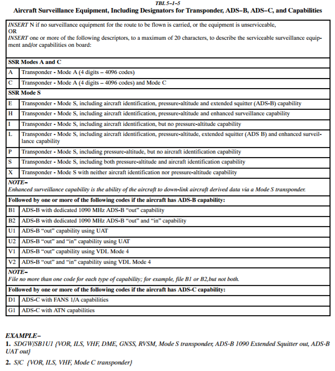
The aircraft equipment section is where it gets complex. Whereas the FAA domestic flight plan had a single letter to designate the entire avionics package, the ICAO system lets the pilot pick and choose the equipment and capabilities specific to their aircraft. Equipment and capabilities that require indication include: Navigation, Transponder, ADS-B, as well as some additional information which may be required in the remarks section.
There are two parts to the equipment box, the first part being the aircraft equipment followed by a slash and the second portion which is the transponder capability. An aircraft can file with an "S" to indicate "standard equipment" which means VHF radio, VOR, and ILS. The use of "S" removes the need to list these three capabilities separately. No capability is encoded with the letter "N". When there is no navigation, communications, or approach capability then file only the letter "N".
For example, if your aircraft had a VHF radio, VOR and ILS, and IFR approved GPS, are able to accept PBN routes and procedures (PBN being a new concept which encompasses both RNAV and RNP, so if you are using RNAV or RNP for any phase of flight this applies) then the final entry into Box 10 would be SGR/C.
It was mentioned earlier that Remarks may be required for PBN aircraft. By listing PBN ® in your equipment you only notified ATC that your equipment is PBN approved. Since PBN describes many different types of equipment you must also specify what exact equipment is onboard in the Remarks Box, number 18. The majority of piston aircraft will enter PBM/B2C2D2, which translates to :
-
B2 = RNAV 5 capability
-
C2 = TNAV 2 capability
-
D2 = RNAV 1 capability
By listing this code you are telling ATC that you are capable of handling RNAV based approaches for the en route structure and terminal procedures. For more information see the following resources.
-
A great, short ICAO flight plan instructional video from AOPA
-
ICAO Flight Plan instructions expected to be included in the 2017 AIM
-
AIM 5-1-9 – International Flight Plan - IFR Flights
Diversion to an Alternate
The day will come when a flight can’t be completed as originally planned. This can be due to weather, equipment failure, poor planning, fuel issues, or pilot/passenger issues. Whatever the issue precautionary termination of a flight if doubt as to the ability to complete it successfully is wise.
Before a flight check the route for suitable alternative stops, and for navaids which can assist during a diversion. Take advantage of all shortcuts and rules of thumb computations when figuring course/speed/distance. Literally use your thumb to measure distance on a standard sectional chart … which each thumb length being roughly 10nm. Use a compass rose, airway, or any other reference to determine the new approximate heading. To select an alternate use the sectional chart, or if appropriately equipped use the "nearest" button on the GPS.
To divert first note the current location on the sectional chart. Divert immediately using the shortcuts and rules of thumb mentioned above. (Spending a lot of time completing all the formal plotting, measuring, and computations first may just aggravate the situation by delaying the diversion.) Once established on course note the time. Use the winds aloft at the diversion point to calculate a heading and GS. Once determined calculate a new arrival time and fuel consumption to the diversion point. Give priority to flying while dividing attention between the tasks of navigation and planning. When determining the new course consider cloud heights, winds, and terrain and adjust the course if needed to address those issues.
Lost Procedures
First, avoid getting lost, but if you do don’t panic. If truly lost practice the Five Cs: Climb, Communicate, Confess, Comply, and Conserve.
| Climb |
Climbing, if able, will allow you to see more ground increasing the chance of spotting a landmark. Climbing also improves radio reception, extends the transmitter rang, and increases radar coverage. |
| Communicate |
Use frequencies on the chart, including RCO frequencies at VOR stations. If identified by a controller they can issue radar vectors. If the situation becomes threatening use 121.5 to call for assistance, and squawk 7700 to alert radar facilities of your distress. |
| Confess |
Now is not the time to play it coy. Tell ATC (if you get in touch with them) exactly what the situation is, and sort out the consequences later when the flight is safely concluded. |
| Comply |
Once in touch with ATC, do what they say. |
| Conserve |
Reduce power/airspee for max endurance or range (whichever makes the most sense in the situation). |
In addition, check the heading indicator against the compass and determine if there is an error. If so, note the error and see if that suggests being right or left of course. Also use any available navigational aids (VOR/ADF) to attempt to plot the position relative to the navaids, thus identifying your location on the chart. GPS can (of course) also be used to determine location. Finally, if you are near a town it may be possible to identify your location by reading the name of the town on a water tower (yes, this has been used, and works).
Conclusion
Cross country flight planning requires a lot of preflight work but the flight itself is worth the time. It also helps to prevent getting lost and keeps us away from potentially dangerous or bad weather.
ACS Requirements
To determine that the applicant exhibits instructional knowledge of the elements of navigation and flight planning by describing:
-
Terms used in navigation.
-
Features of aeronautical charts.
-
Importance of using the proper and current aeronautical charts.
-
Method of plotting a course, selection of fuel stops and alternates, and appropriate actions in the event of unforeseen situations.
-
Fundamentals of pilotage and dead reckoning.
-
Fundamentals of radio navigation.
-
Diversion to an alternate.
-
Lost procedures.
-
Computation of fuel consumption.
-
Importance of preparing and properly using a flight log.
-
Importance of a weather check and the use of good judgment in making a “go/no-go” decision.
-
Purpose of, and procedure used in, filing a flight plan.