Lesson Overview
The student should develop knowledge of the elements related to the principles of flight. The student should understand why airplanes are designed in certain ways as well as the forces acting on airplanes and the use of those forces in flight.
References : Airplane Flying Handbook (Chapter(s) : 1), Pilot’s Handbook of Aeronautical Knowledge (FAA-H-8083-25C, page(s) 5-30)
| Key Elements |
|
| Elements |
|
| Schedule |
|
| Equipment |
|
| IP Actions |
|
| SP Actions |
|
| Completion Standards |
The student understands the principles to flight. |
Instructor Notes
| Attention |
Everything you ever wanted to know about the science of the airplane which will result in a considerably better understanding of the airplane and make you a considerably better pilot. To know why we do what we do, you need to know why the airplane does what it does. |
| Overview |
Review Objectives and Elements/Key ideas |
| What |
The Principles of Flight are the characteristic forces of flight as well as why and how the airplane performs certain ways. |
| Why |
To become a pilot, a detailed technical course in the science of aerodynamics is not necessary. However, with the responsibilities for the safety of passengers, the competent pilot must have a well-founded concept of the forces which act on the airplane, and the advantageous use of these forces, as well as the operating limitations of the particular airplane. |
Lesson Details
Many forces act on an aircraft in flight, and many of these forces work in concert to give desired handling characteristics. A good understanding of how these forces work, and how they combine to give the results desired is crucial to understanding the nuances of flight.
Airfoil Design Characteristics
The basic starting point in describing an airfoil/wing is the characteristic known as the planform. This is the term that describes the wing shape as seen from above, and it defines the basic characteristics of the wing. The shape is selected with design goals in mind, and at times some shapes are combined to achieve specific outcomes.
One attribute of shape is taper, which is the ratio of the root chord of the wing to the tip chord. Rectangular wings have a taper of 1, and are simpler to build (all the ribs are the same size), and generally the root stalls first giving more warning and control in the stall recovery. An ellipse planform, on the other hand, gives the best span wise load distribution and least induced drag, but is much more complex to build (each rib is different).
Another attribute of shape is aspect ratio, which is the ratio of length of wing to the chord. Longer/narrower wings have a high aspect ratio and have less induced drag (resulting in more lift for the wing area). Wingtips are smaller so they have less wingtip vortices, but the long wings make the aircraft less maneuverable.
A final attribute of shape is sweep, which is the line connecting the 25% chord points of the ribs isn’t perpendicular to the longitudinal axis of the aircraft. The sweep can be forward, but is usually backward, and it helps in high speed flight but can also contribute to lateral stability in low-speed planes as well.
Airplane Stability and Controllability
The two attributes, stability and controllability, are described with a number of different dimensions, and the two can .. at times .. be in opposition to each other. Controllability describes the capability to respond to the pilot’s inputs especially with respect to flight path and altitude. Maneuverability describes the quality that permits the aircraft to be maneuvered easily and withstand stresses imposed (often determined by the weight, inertia, size/location of flight controls, structural strength, and power plant).
Stability is the inherent quality of an aircraft to correct for conditions that may disturb it’s equilibrium. A stable plane will return to it’s initial condition after being disturbed, and the more stable the easier an aircraft is to fly, but that increased stability may result is reduced maneuverability. Therefore the two must be balanced in the design of the aircraft. There are two types of stability, static and dynamic stability. An aircraft in equilibrium has all forces in balance, and the two types of stability are described by how the aircraft responds when that equilibrium is upset.
Static Stability
This is the initial tendency displayed by the aircraft when equilibrium is disturbed.
- Positive static stability
-
This is described by an initial tendency to return to the original state of equilibrium after being disturbed. This is the most desired type of aircraft stability.
- Negative static stability
-
This is the initial tendency to continue away from the original state of equilibrium after being disturbed.
- Neutral static stability
-
This is the initial tendency to remain in a new condition after equilibrium has been disturbed.
Dynamic Stability
While static stability refers to the initial response to an upset of equilibrium, dynamic stability refers to how the system responds over time. It describes whether the system returns to equilibrium over time, and the degree of stability is described in terms of how quickly it returns to equilibrium (assuming it does).
Dynamic stability can also be divided into oscillatory and non-oscillatory modes. Oscillatory describes the motion of a marble in the bottom of a smooth bowl where if it is disturbed it eventually returns to rest back at the bottom of the bowl. This describes a system that exhibits both positive static stability and oscillatory positive dynamic stability. The longer the oscillations in time, the easier the aircraft is to control Neutral or divergent short oscillation is dangerous as structural failure can result. Non-oscillatory can be described by replacing the marble with a cotton ball, and the system returns to rest with no oscillations.
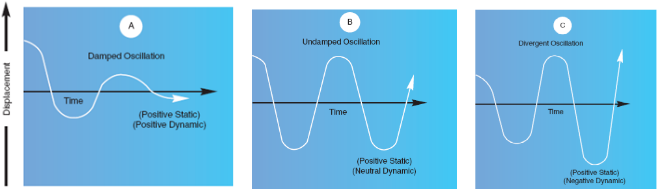
The image above shows the flight path of an aircraft with various combinations of static and dynamic stability.
Longitudinal Stability
Longitudinal stability describes the stability around the pitch axis. A plane that is longitudinaly unstable tends to dive and climb progressively steeper making it difficult (or dangerous) to fly. To achieve this stability it must be the case that if disturbed the wing moments and tail moments will change so their forces provide a restoring moment bringing the nose back into the proper attitude again.
Static longitudinal stability is dependent upon three factors: the location of the wing in relation to the center of gravity, the location of the horizontal tail with respect to the center of gravity, and the area/size of the tail surface.
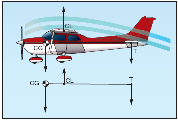
The wing is usually behind the center of lift, which results in a nose down pitch force. This nose heaviness is balanced by a downward force generated by the tail. This is due to the fact that the tail is designed with negative AOA to create a natural tail-down force. This creates a situation which resembles a lever where the tail lifts the nose pivoting around the CG. The stronger force is at the CG and the tail force is weaker, but has a longer lever arm.
If the nose is pitched up airspeed will decrease, and therefore the down force on the tail will decrease. This allows the nose to pitch back down. If the nose goes down the speed increases and the down force on the tail increases, raising the nose again. If left untouched this oscillation will continue dampening out with each cycle until the aircraft reaches equilibrium again.
The center of gravity impacts stability because of it’s relation to the horizontal tail surface. If the plane is loaded with the CG forward, more tail down force is needed to balance which adds to longitudinal stability. If the reverse loading is the case then the CG goes back, the force on the tail is lightened. In extreme cases where the CG is moved behind the CL, it will create a situation where a pitch up will cause less airflow over the tail, causing the nose to pitch further, and ultimately causes the plane to be uncontrollable.
Lateral Stability
Lateral stability describes the stability around the roll axis. Stability around this axis is impacted by dihedral, sweepback angles, keel effect, and weight distribution.
Dihedral is the angle at which the wings are slanted upward from the root to the tip of the wing. This angled arrangement causes the wings to be at a different angle of attack when the plane rolls, with the low wing being at the greater AOA. This increased AOA causes the low wing to generate more lift, thus rolling the plane back upright, returning to straight-and-level flight.
Sweepback is the angle at which the wing are slanted to the rear of the aircraft from the root to the tip. This has a similar affect to dihedral, but the effect is rather less pronounced.
Keel effect is the action of the relative wind on the side of the plane. If the greater portion of the "keel" is above and behind the CG then the relative wind’s pressure on the keel has a tendency to roll the aircraft back to a level attitude. In short, keel effect forces the plane to parallel the relative wind.
Weight distribution impacts lateral stability by the simple expedient of where the weight is placed. If it is placed to one side, it can cause the aircraft to have a tendency to roll to that side.
Directional Stability
Directional stability is affected by the area of the vertical fin and the sides of the fuselage fat of the CG. These components make the aircraft behave as if it were a weather vane, pointing the nose into the relative wind.
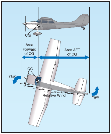
Of course, for a weather vane to work the side surface must be greater aft of the pivot point (in the case of the plane, this is the CG). In addition to this weather vane effect the vertical stabilizer acts like a feather on an arrow. The further aft the fin is place the greater stabilizing force will be exerted due to the longer lever arm.
Turning Tendency
There are a number of dynamic forces which create a characteristic left turning tendency. This tendency is fed by four factors: torque reaction, corkscrew effect of the slipstream, gyroscopic action of the prop, and P-factor. I should note that the following discussions are true in aircraft whose propellers turn clockwise as viewed from inside the cockpit.
Torque Factor
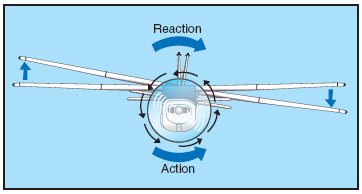
Newton’s third law says that for every action there is an equal and opposite reaction. Therefore as the propeller rotates one way, it creates a force in the opposite direction. When airborne this force acts around the longitudinal axis resulting in a left rolling tendency. On the ground during takeoff the left side is being forced down resulting in more ground friction, causing a turn to the left (and the higher the power setting, the more force is exerted).
Torque is countered by various methods. The engine can be offset somewhat. The ailerons and rudder can have trim tabs. But any force not designed out with these tools must be offset with appropriate rudder and aileron inputs.
Corkscrew Effect
The high-speed rotation of the propeller sends the air backward along the aircraft in a corkscrewing manner. As this happens the air strikes the side of the vertical stabilizer pushing the nose of the aircraft left.
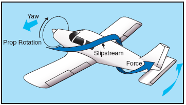
At high prop speeds and low forward speeds this rotation is very compact which exerts a strong sidewards force on the vertical stabilizer. There is also some rolling force imparted as well, which is to the right and which may counter some of the left turning tendency. As speed increases the spiral elongates reducing its effectiveness. These forces are also countered with coordinated rudder and aileron inputs.
Gyroscopic Action
Gyroscopes are based on two fundamental principles: rigidity in space (not a key factor in the current discussion) and precession. Precession is the resultant action of a spinning rotor when force is applied to it’s rim. If a force is applied it takes effect 90 degrees ahead of, and in the direction of, the spin.
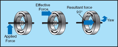
In the case of an aircraft this can cause either a pitch or yaw moment (or a combination of the two) depending upon where the force is applied. This is most apparent in a tailwheel aircraft when the tail is raised, and the prop disk is therefore pitched upright. The change in pitch (lifting the tail) has the same effect as applying a forward force to the top of the propeller. This force is felt 90 degrees clockwise (when viewed from inside the cockpit), which has the force taking effect on the right side of the propeller, imparting a left turning force.
This also means that any pitching around the lateral axis will result in a yawing moment, and a yawing around the vertical axis will create a pitching moment.
P-Factor
The term p-factor refers to the asymmetric loading of a propeller when operating at high angle of attacks. This has the net effect of moving the center of thrust to the right of the propeller disc, and is due to the "bite" of the down-going blade being greater than the "bite" of the up-going blade.

Looking at the image above you can see that when the propeller is straight upright the forces are equal all around. However, as the angle of attack increases the pitch of the blades with respect to the relative wind changes, with the down-going blade having a greater angle of attack. This generates more force, thus shifting the center of the aggregate force toward the side with the higher angle of attack.
Load Factor
The load factor is the force applied to the aircraft to deflect it form straight flight that places load on the airframe. It is also the ration of the total air load acting on the airplane to the gross weight of the plane. As example, a load factor of three means that the total load on the structure is 3x it’s gross weight, often expressed as "3 Gs". Subjecting your plane to a load of positive three Gs causes you to be pressed into your seat with three times your weight.
The load factor is important to the pilot for various reasons. An increasing load factor also increases the airspeed at which the aircraft stalls. It can make the plane stall at what are normally seemingly safe speeds. At the extreme too high a load factor can cause the structure to fail.
The strength of the structure is generally determined by the design goals for the aircraft. This is always a compromise, as designing to higher loads often means stronger (bulkier, heavier) structures, which results in less useful load. A lighter more efficient structure can mean one for which loads must be carefully managed to avoid airframe failure. Therefore airplanes are designed with a standardized category system in mind :
| Normal Category |
Limited to -1.52 Gs to 3.8Gs |
| Utility Category |
Limited to -1.76 Gs to 4.4 Gs (includes mild aerobatics and spins) |
| Aerobatic Category |
Limited to -3.0 Gs to 6.0 Gs |
The more severe the maneuvers, the higher the load factor imposed.
The Vg diagram shows the flight operating strength of a plane that is valid for a certain weight and altitude.
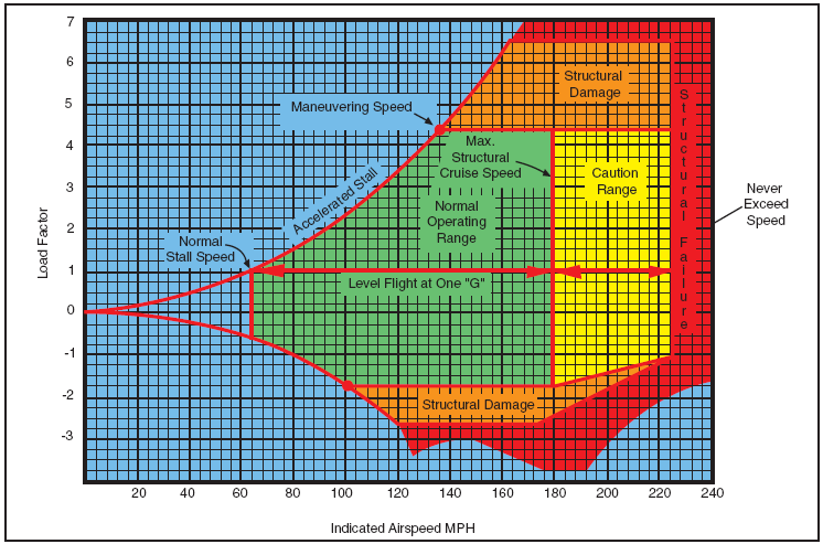
This diagram depicts the allowable combination of airspeed and load factor for safe operation. While it may seem a bit "busy", it can be a very informative diagram and is worth understanding.
The L/D Diagram compares the two types of drag that predominates in flight, induced drag and parasitic drag. Induced drag is a component of total drag that arises whenever a finite span wing generates lift. At low speeds an aircraft has to generate lift with a higher angle of attack, thereby leading to greater induced drag. This term dominates the low-speed side of the lift versus velocity graph.
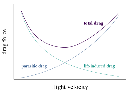
Parasitic drag is caused by movement of the aircraft through the air. This type of drag, also known as air resistance or profile drag varies with the square of speed. For this reason profile drag is more pronounced at higher speeds, forming the right side of the lift/velocity graph’s U shape. Profile drag is lowered primarily by streamlining and reducing cross section.
Lift, like drag, increases as the square of the velocity and the ratio of lift to drag is often plotted in terms of the lift and drag coefficients CL and CD. In this diagram speed increases from left to right, and drag increases from bottom to top. The lift/drag ratio is given by the slope from the origin to some point on this curve and so the peak L/D ratio does not occur at the point of least drag, the leftmost point. Instead it occurs at a slightly higher speed.
Wingtip Vortices
Whenever a wing is producing lift the pressure on the lower surface is higher than the pressure on the upper surface. Air tends to flow from the high pressure area to the lower and during flight this means that air "spills" off the tip of the wing and tries to roll up onto the top. The result is a swirling mass of air trailing the aircraft.
The strength of this vortex is determined by the weight of the aircraft, the speed of the aircraft, and the shape of the wing. AOA directly affects the strength and as weight increases, AOA increases. Also if the wing is "clean" (i.e. has no lift augmentation devices such as flaps and slats deployed) it has a greater AOA. Finally, as speed increases AOA decreases. Therefore the strongest vortex is when the aircraft is heavy, clean, and slow. (i.e. during takeoff and landing).
Vortexes sink at a rate of a few hundred feet per minute, and slowing/diminishing as they get further from the aircraft. When they sink to the ground they tend to move laterally with the wind. This means that winds can bring a vortex into your landing path, so be aware!
The vortexes are the cause of "wake turbulence" and are to be avoided. At a minimum they can make for an uncomfortable ride, and at the worst they can induce unintended aerobatics or structural failure. This is most often a problem when a light aircraft is operating near a heavy jet transport, which can generate very strong vortexes. The vortexes can be avoided by a number of techniques.
During landing stay above the flight path of the aircraft in front of you, and land beyond that aircraft’s touchdown point. For parallel runways stay at and above the other aircraft’s path, and for crossing runways cross above the other aircraft’s path.
During takeoff delay liftoff until after the jet’s touchdown point, and takeoff and stay above another departing jet’s path. Note that the climb rate for most jets exceed those of light aircraft, so a turn away from the departing aircraft’s path may be mandated to avoid wake turbulence.
Conclusion
The competent pilot must have a well-founded concept of the forces which act on the airplane, and the advantageous use of these forces, as well as the operating limitations of the particular airplane.
ACS Requirements
To determine that the applicant exhibits instructional knowledge of the elements of principles of flight by describing:
-
Airfoil design characteristics.
-
Airplane stability and controllability.
-
Turning tendency (torque effect).
-
Load factors in airplane design.
-
Wingtip vortices and precautions to be taken.